Saike 858D++ - First Block Diagram
After a short break, here is the first part about the redesign of the Saike 858D rework station (Overview).
Let’s talk about a rough block diagram for the new design.
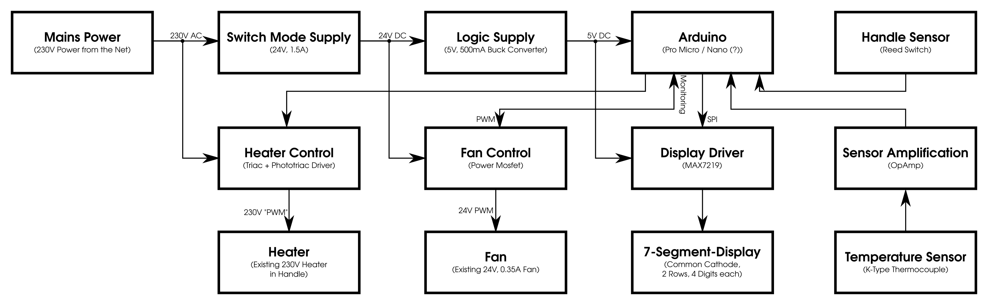
Let’s have a look at the general structure and first follow the path of the power supplies. Twe build a mains powered device so we start with that at the top left. The mains power is fed into the heater control circuit as well as a 24V switch mode power supply, which I will use to replace the transformer.
The 24V power supply is connected to the fan control circuit and another switch mode supply, this time providing a 5V rail. The 5V supply is used for an Arduino board, which will be plugged on the main PCB. I have not yet decided which model I want to use, but it will probably be one of the Pro Micro or Nano boards I have lying around. Additionally, the 5V supply is used for the other logic level components, like the display and the sensors.
The Arduino is connected to the heater and fan control circuits, both regulated through some form of PWM. The heater control will use more or less the same design as the original, regulating the heater through a optocoupled triac. The fan control will use regular PWM to switch a power mosfet that can in turn regulate the fan supply. Additionally, there will be a form of monitoring of the fan speed. I am currently pondering which way I want to go there.
The display will be replaced by two 7-segment displays with 4 digits each. The displays are controlled by a MAX7219 IC, which is connected to the Arduino through SPI.
The sensor inputs from the handle sensor and the thermocouple are fed into the Arduino directly and are used in the control loop.
That’s about it. There is still some uncertainty about some desin points, but I am feeling confident that this should, at least roughly, work.