Reverse Engineering the Saike 858D Rework Station
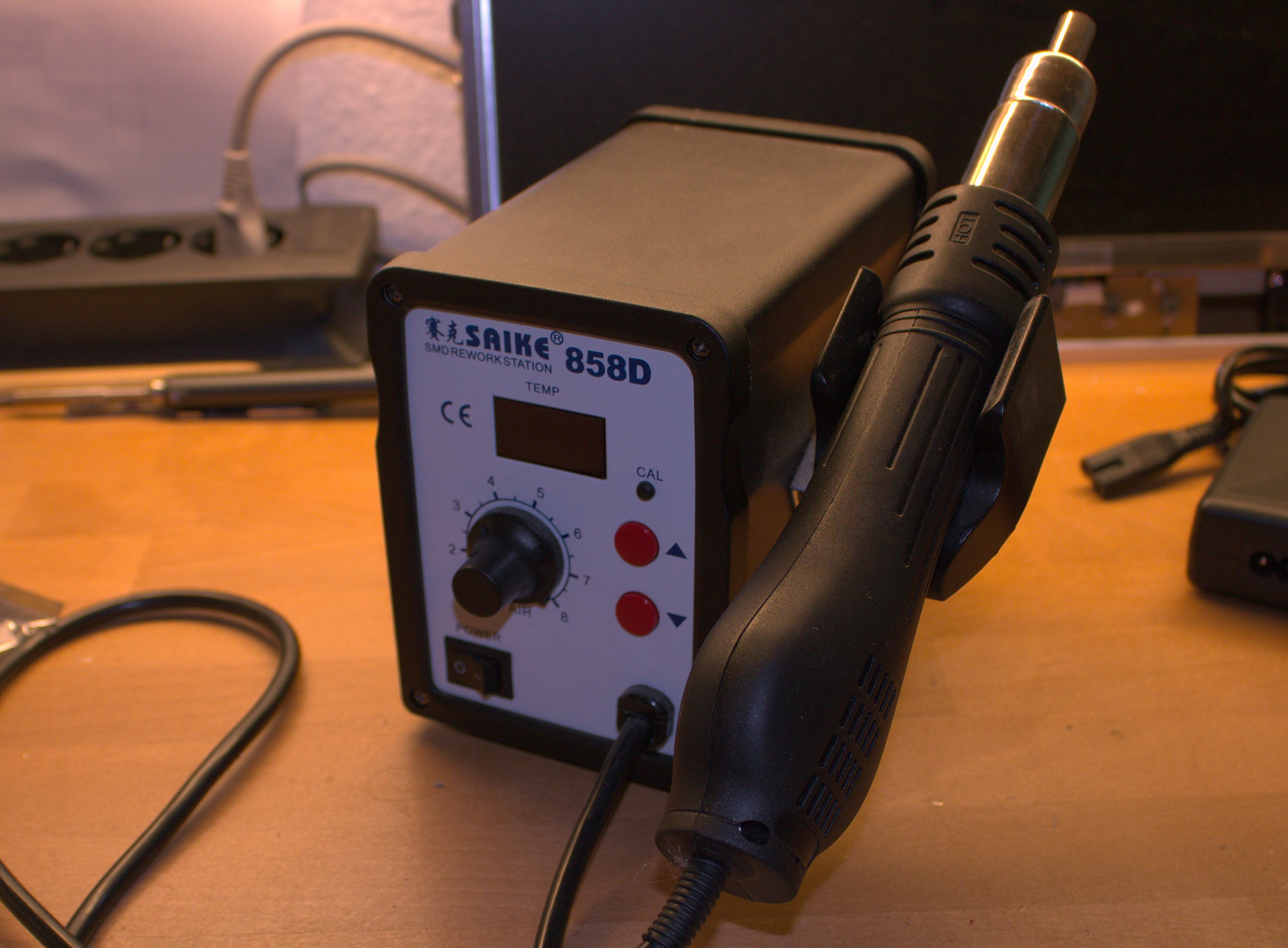
Quite some time ago I bought an SMD Rework Station at AliExpress. The station I ordered was a Saike 858D, which is one of the numerous versions of the 858D line of rework stations. The “original” model is probably the Atten 858D+ which Dave Jones from the EEVBlog also did a tool review on. My station was really cheap and I am, in general, glad that I have it.
However, as usual with cheap equipment, there is also a bit room for improvement. That is what I am trying to do here.
Contents
This first post will not cover everything so here is a Table of Contents where I can link the next posts:
- Mission Statement and Teardown (This)
- Reverse Engineering
- …
Problems
Let’s start with the problems I see with the station.
- The temperature control is not very exact. The heating is very quick, but (I think) overshoots quite a lot. I measured the temperature at the nozzle with an external thermocouple. When the device was set to 200 °C it measured more than 250°C before I removed it from the airflow to prevent damaging the probe.
- The display doesn’t show any meaningful information. When you change the target temperature it is shown on the display. During operation it looks like the temperature is the current air temperature, but the display usually just continuously shows the target temperature.
- When putting the handle back, the heater is turned of and the fan keeps on running until the temperature falls to 100 °C at which point the fan turns off. However, due to the heat capacity of the heater element and the nozzle, the temperature rises again significantly. I would like the fan to keep on running for some time to really cool the tool down. I don’t want to burn down the house I live in.
Other people doing this stuff
There have been some other people working on more or less the same project.
- Spitzenpfeil has torn down the YouYue 858D+ and found an ATMega microcontroller inside which he reprogrammed and also modified a bit on the main PCB.
- Christean over at heartoftechnology has reverse engineered the Hylko 858D and started a complete redesign of the circuit board. I learned quite a lot from that work, so big thanks to him.
- wguibas on the EEVBlog forum has created an adapter board for the Yihua 858D
Goal
I would like to solve all or most of the problems mentioned above. My first idea was just a similar approach to wguibas, designing a small adapter board and reuse all the rest. But when I stumbled upon Christean’s initial plans to create a complete new PCB I kind of liked that idea so I think I will take it up where he left it off.
But first, to understand what is really going on in the station, I need to tear my station down and have a look what I got.
Tearing it down
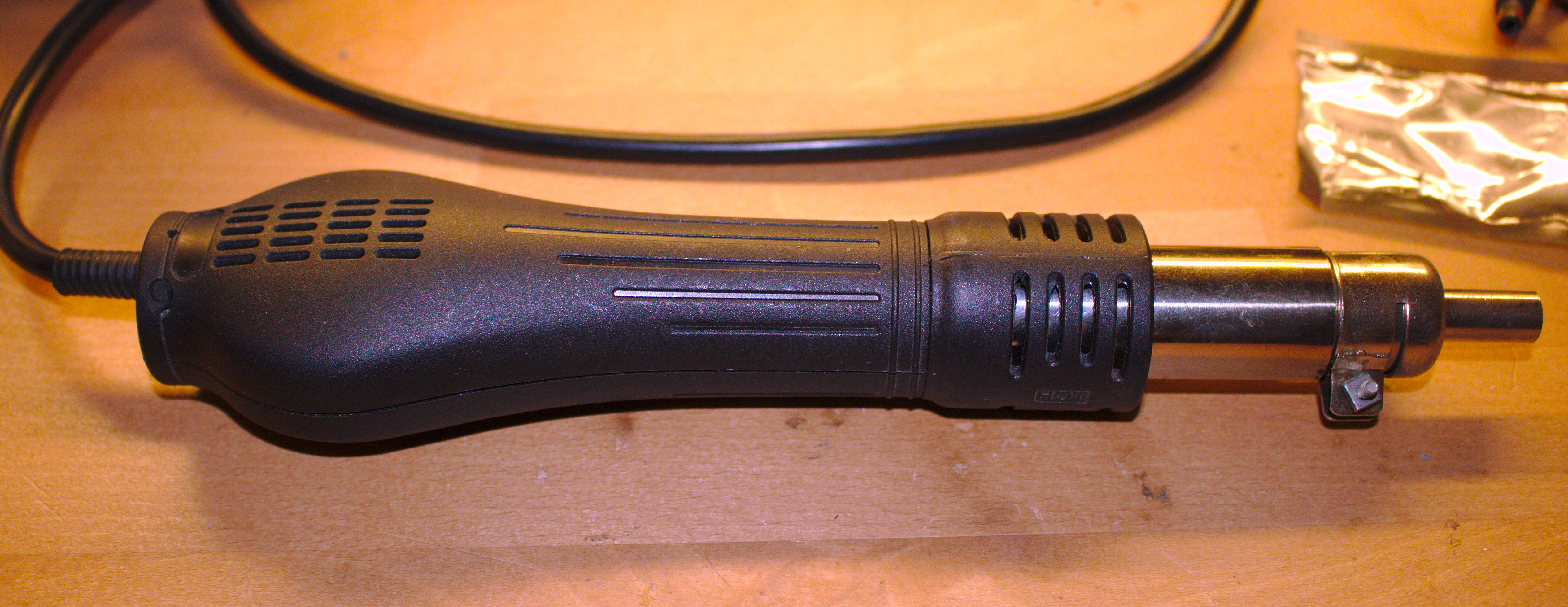
The external housing is quite okay. At the front of the device we have a knob for controlling the fan speed and two buttons for setting the desired temperature. At the corners, we have a (single-pole) switch to turn off the device and the fixed cord to the handle. Some of the other “flavors” of the device have a detachable handle. However, these versions might expose live mains voltage on the connector if the handle is not connected.
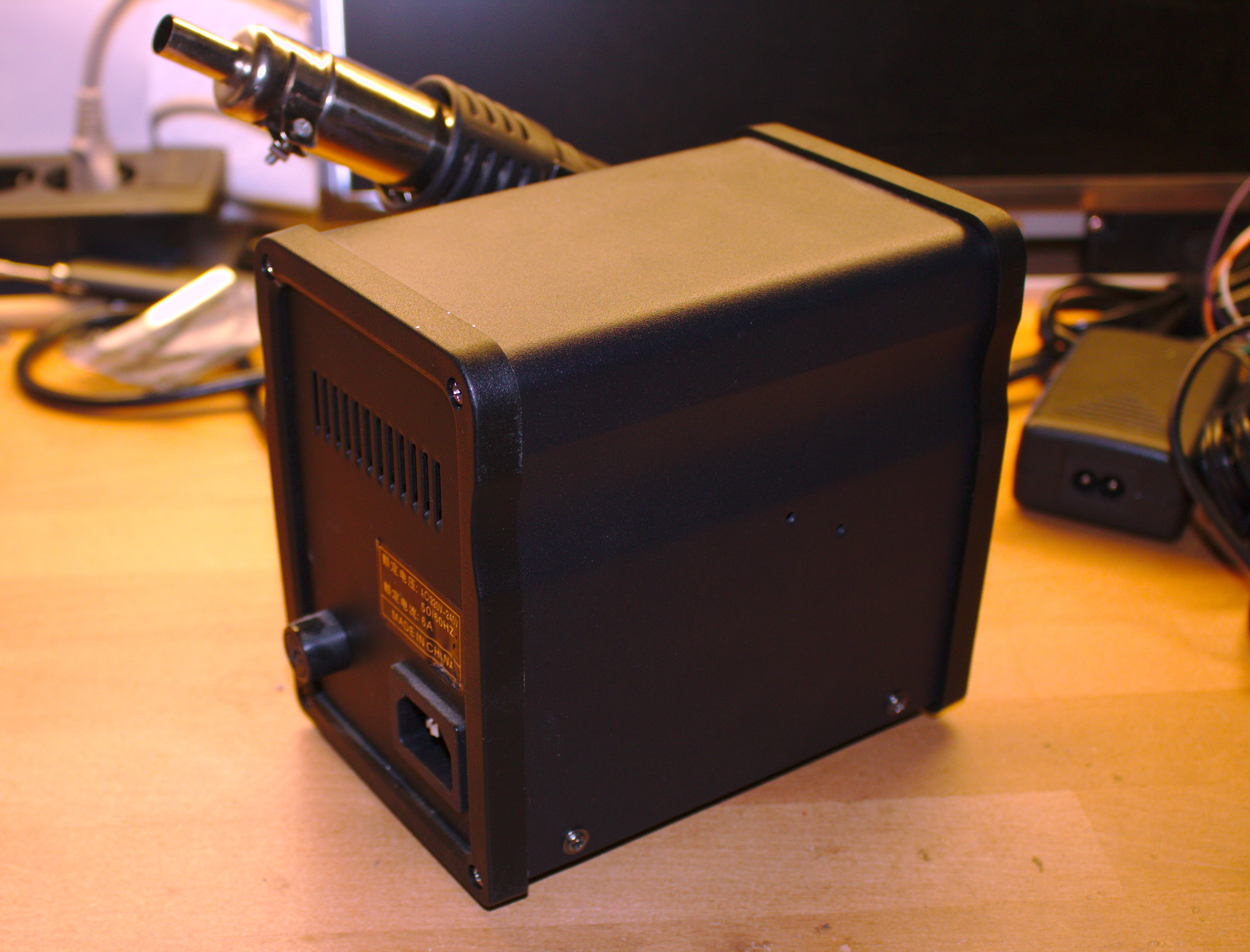
At the back, we can see a fuse holder and an IEC C14 terminal. The C14 terminal wasn’t on the device when I bought it, but the power cord was fixed. This cord I replaced quite some time ago.
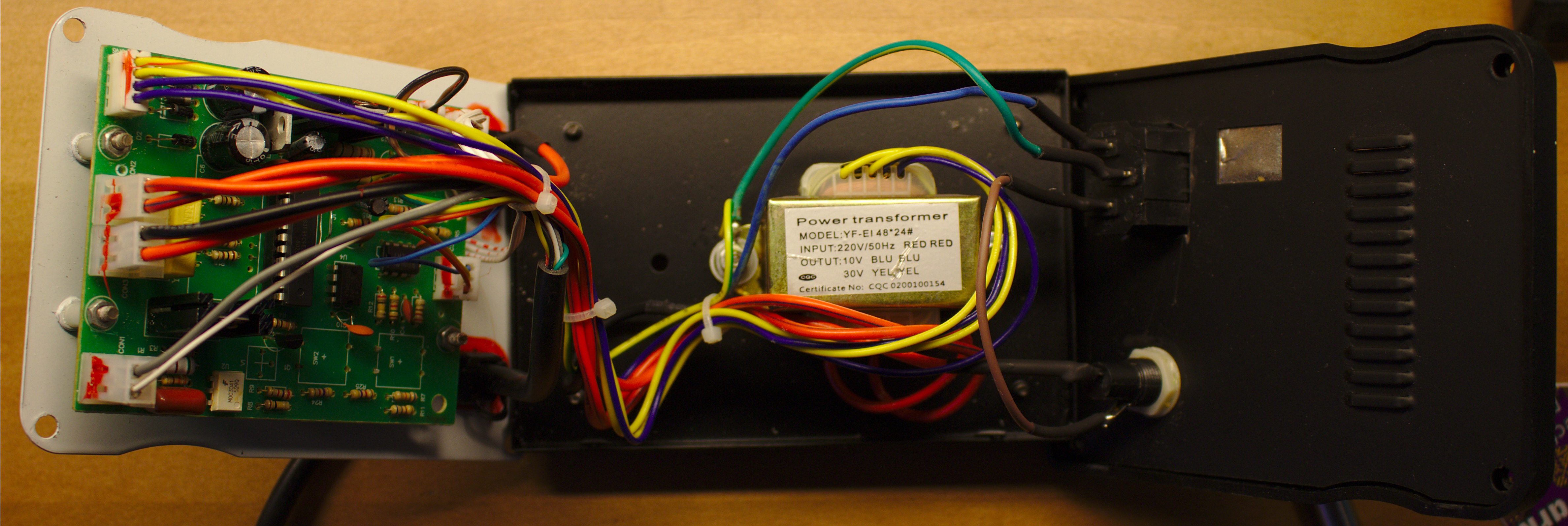
If we look at the interior, we see the power terminal is connected to the fuse holder and then fed through the power switch and into the main PCB. AT the center of the unit we have a power transformer which produces 10V and 30V outputs. The transformer is powered through the main PCB.
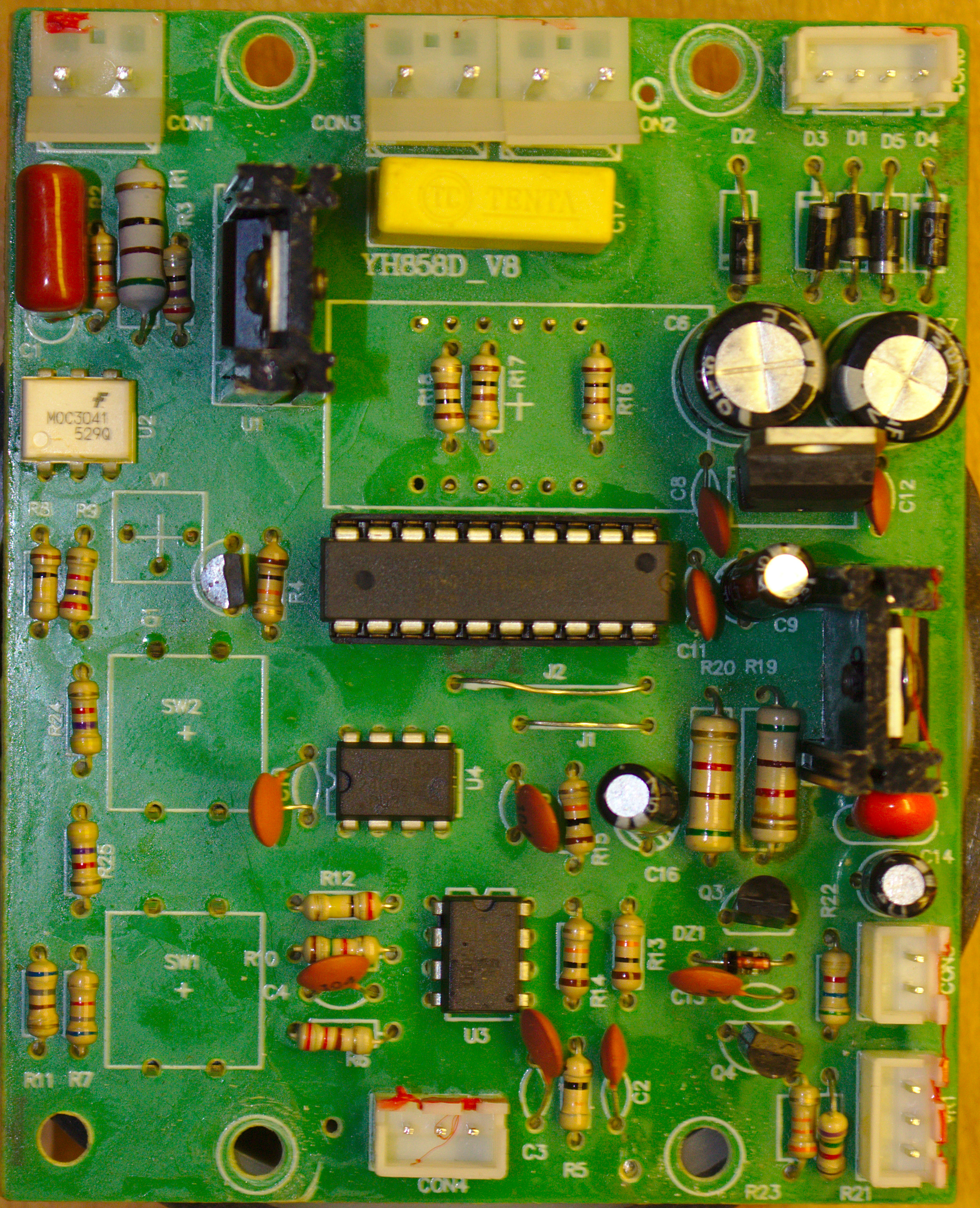
The main PCB is a single-sided PCB with through-hole components. We have a high voltage section in the top left corner, sadly without any insulation slots in the board. The mains power is connected at the connector at the top. The components in the top left corner are responsible for the mains switching for the heating element. The top right corner hosts the lower voltage regulation for the fan and the logic components. At the bottom right we see the components for the fan control.
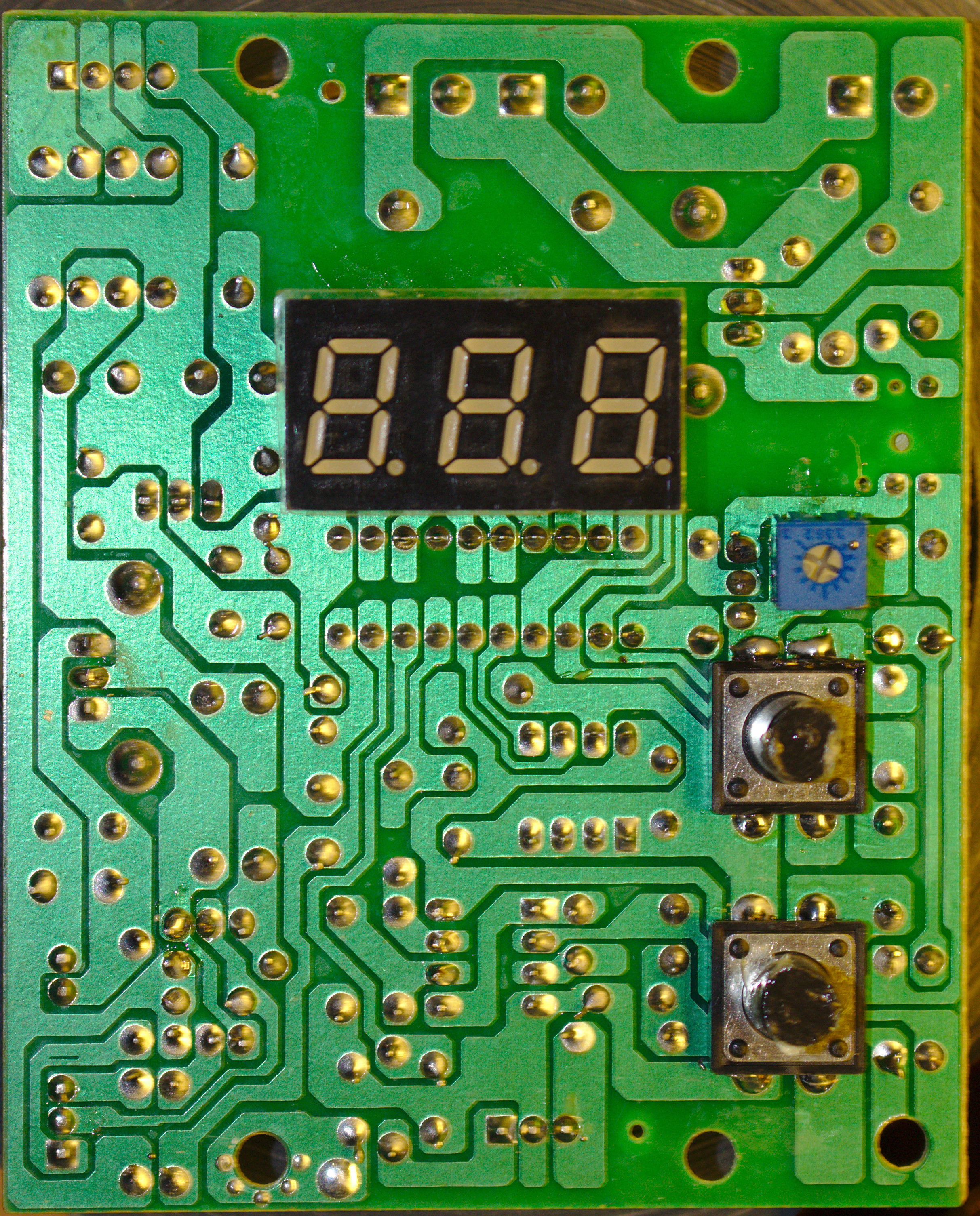
On the back side we don’t have too many surprises. The components on this side are used as the user interface. We can also see that, even though there are no insulation slots for the mains voltage area, there is a good clearance.
Let’s look at a few components in detail. The main microcontroller at the center of the board is a S3F94C4EZZ (Datasheet), which I have no experience with.
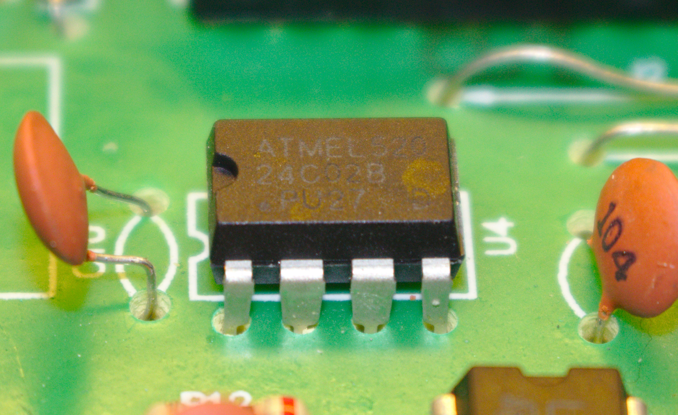
According to the datasheet, the MCU has no persistent memory apart from its program memory. This leads to the addition of an external EEPROM chip. The EEPROM is an Atmel 24C02B (Datasheet) with a capacity of 2 KB of memory. I assume it is used to store the set target temperature across reboots.
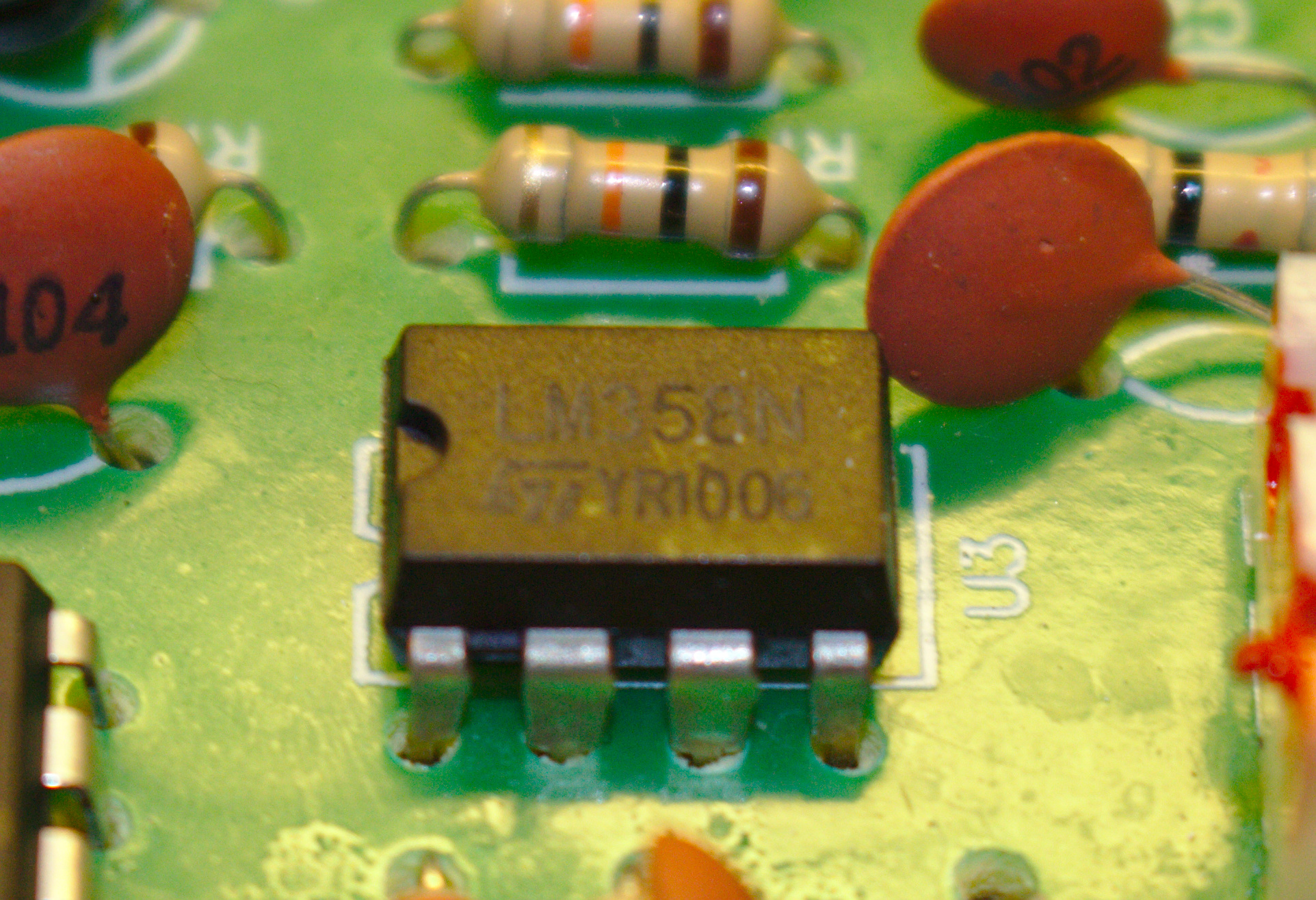
Next to the EEPROM we can find a small dual OpAmp chip, the LM358N (Datasheet). The OpAmp is connected to the sensor input from the handle and amplifies the sensor data from the thermocouple.
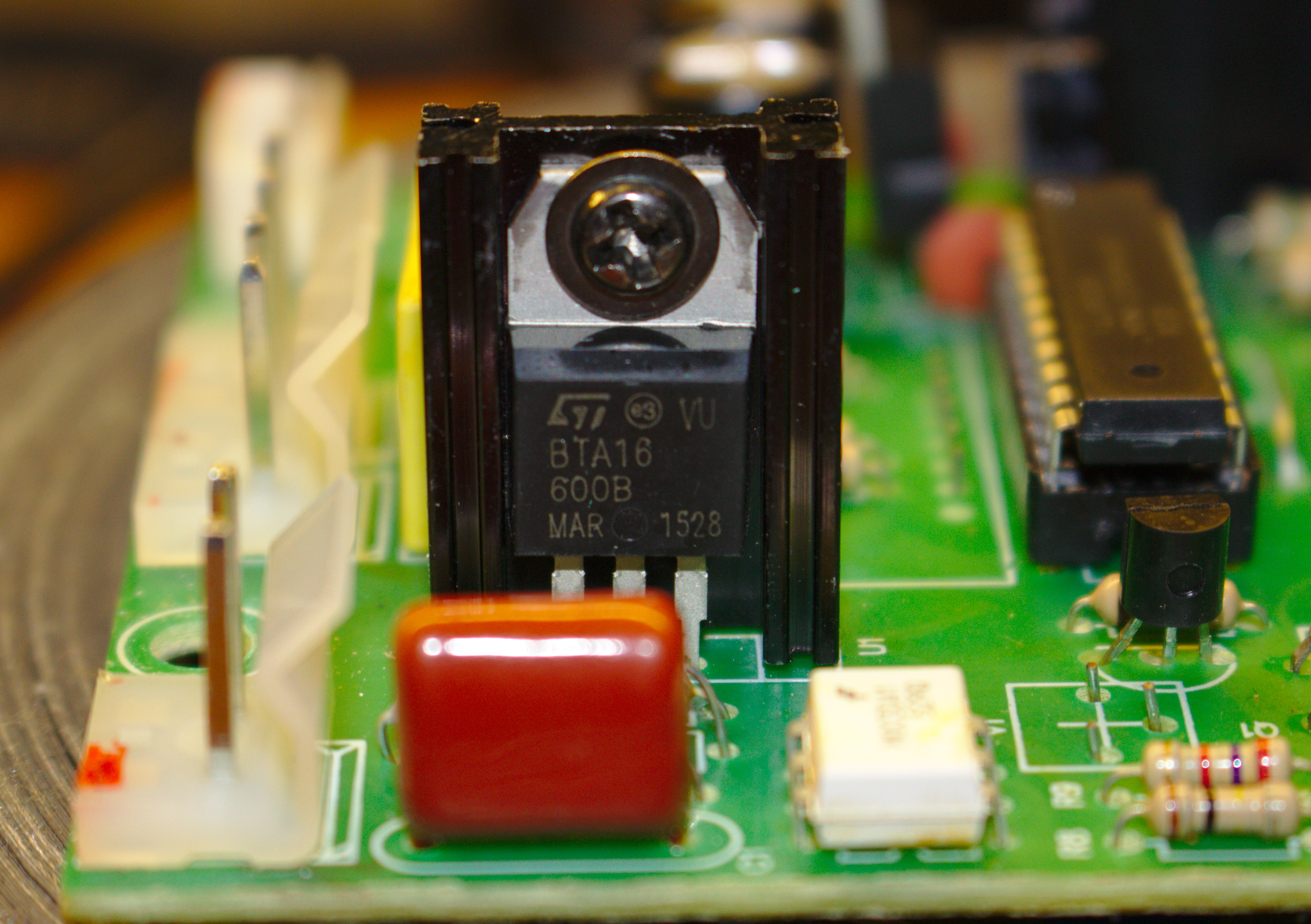
The mains switching is performed by a BTA16 triac (Datasheet) which in turn is controlled by an opto-isolated triac, specifically the MOC3041 (Datasheet).
In the handle we don’t have too many active components.
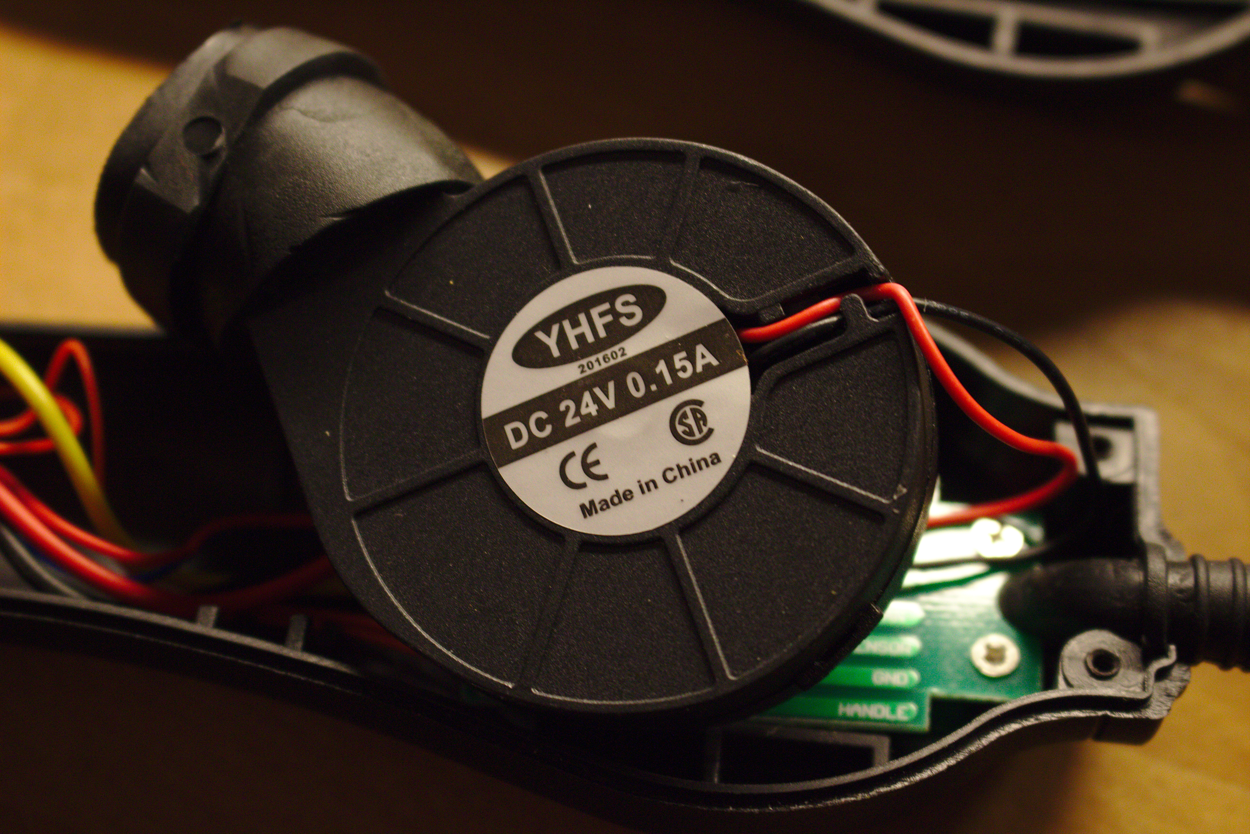
The fan is a fairly standard blower that is fed through a small PCB in the handle.
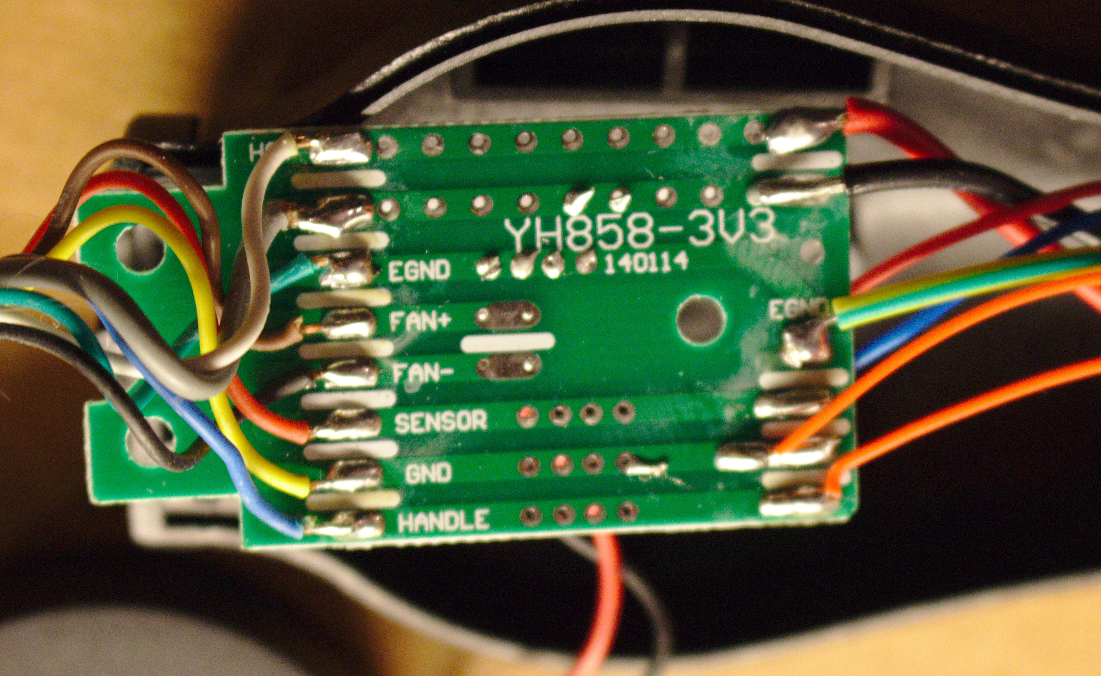
All wires are connected to the PCB. The traces at the top carry mains voltage and look fairly thin. Also the wires don’t look too great for a high voltage application.
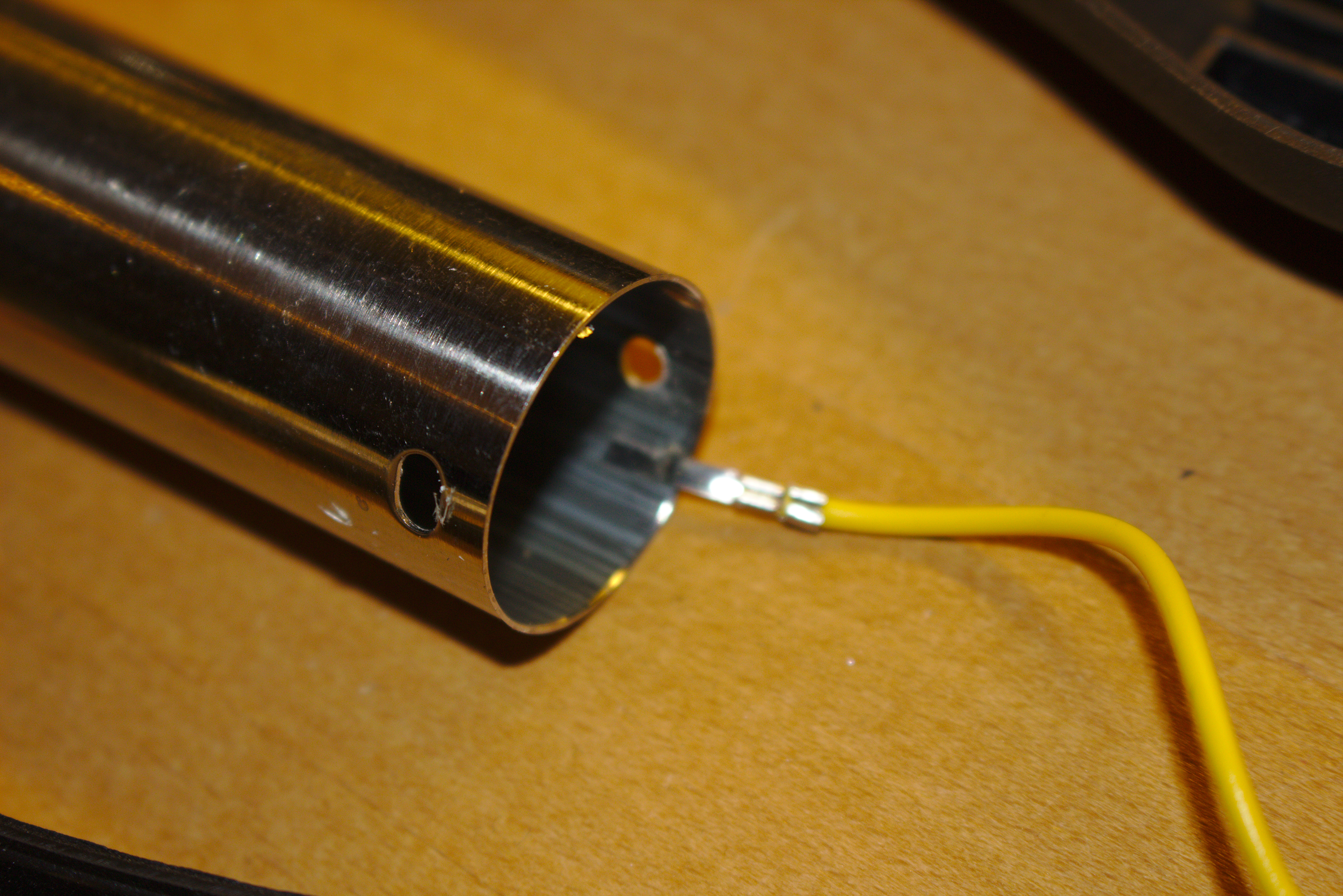
The metal housing of the nozzle is properly connected to protective earth. In other devices this connection was really bad, so I am glad with the solution in my device.
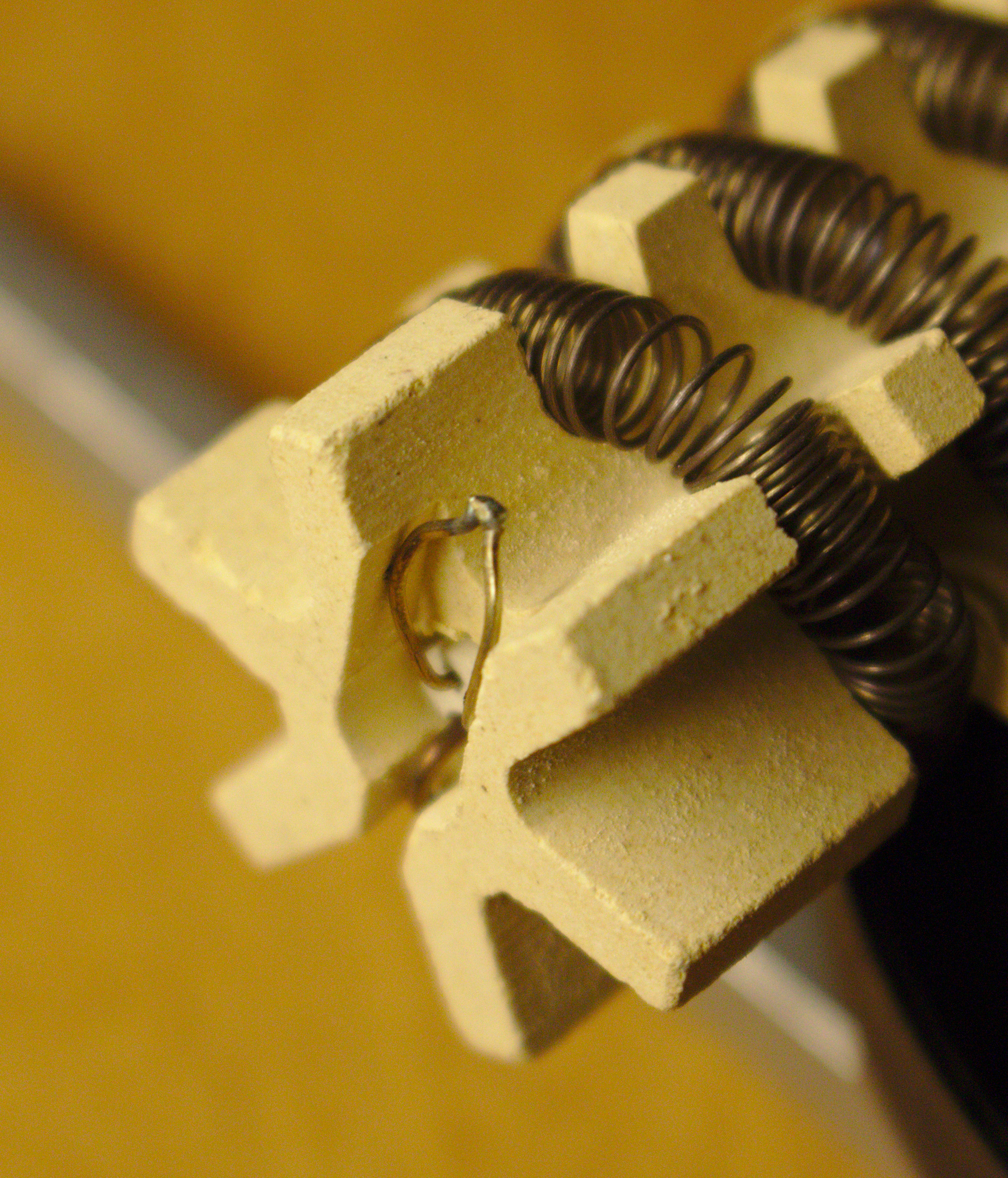
The heater is a fairly large ceramic element with a heating coil wrapped around. Right at the front we can find a thermocouple for the temperature control. The placement of the thermocouple leads to an offset between the measured temperature and the real temperature at the nozzle.
That’s all for the teardown. The next step is reverse engineering the circuit board and understanding what is going on.